
Guide: How an induction hob is made |
Rispondi 
|
| Autori | |
Cristiano Passeri 
Admin Group 
Amministratore registrato: 31 Dic 2006 Stato: Offline Points: 3810 |
 Opzioni Post Opzioni Post
") Grazie(0) Grazie(0)
 Quota Rispondi Quota Rispondi
 Argomento: Guide: How an induction hob is made Argomento: Guide: How an induction hob is madePostato: 06 Lug 2015 alle 13:44 |
|
How an
induction hob is made First issue: 5 June 2015 Last update: 23 February 2017 Here we can see how an induction hob is built and how it works. The model examined here is an AEG 68001 K-MN, produced in year 2009. The most of what is written here is valid for all the current models (2015) produced by the 2 major German manufacturers groups (AEG/Electrolux, Bosch/Siemens/Neff). The assembling layout and the electronic boards are very similar. The operation principles related to the inverters and induction coils are generally valid for all manufacturers. The small and cheap portable induction cookers differ in several parts from these devices. The induction hobs by AEG/Electrolux and Bosch/Siemens/Neff, at least the new models presented from the year 2009, use electronic boards of the same generation of these shown here. This generation is more reliable then the previously. Photo: The induction coils: - After removing the stainless steel frame and the ceramic glass, the induction coils and the control panel are naturally placed on the upper level. The
induction coils are covered with a thin sheet made with a material containing Glimmer, a mineral material very resistant to high temperatures. The upper side of the sheet is reflective, to reject away from the coil the heat coming down through the ceramic glass from the bottom of the pot. Photo: Ceramic glass removed
Under the reflective sheet is placed a disc made of a heath insulating material, about 2-3 mm thick. This insulating disc has the function to protect the induction coil from the heat coming down from the pot and to avoid that too much heat comes inside of the device. When cooking by high temperatures using oils or without fats, the glass reaches over 200°C (392°F).
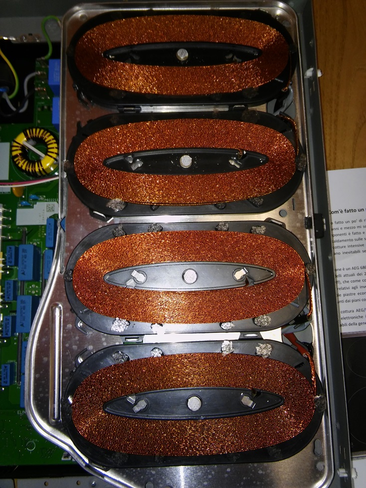
Photo: Induction coils 
Once
removed
the
thermal
insulating
material,
the
induction
coils
are
visible.
In
this
model
the
coils
are
fixed
with
glue
on
a
sheet
made
with Glimmer.
Under
of
it,
4
rectangular ferrite
bars
are fixed,
oriented
in
sunburst
way.
These
bars
push
up towards the pot the
part
of
magnetic
field that
would
tend
to
spread
in
the
direction
below
the
coil.
This
helps
also
to
overcome
the
actual
distance
between
the
coil
and
the
bottom
of
the
pot.
The coils8cm and 21cm cooking zones are made with 24 and 26 whorls with copper wire of about 3 mm diameter. The coil of the 14,5cm zone is made with 26 whorls with copper wire of about 2 mm diameter. The diameters of the coils actually match with the nominal diameters of the cooking zones here, differently than in the portable induction cookers which I have seen. The induction coil of the 21 cm zone has a space among the whorls in the middle part. This is to improve the spreading of the heat in along the whole diameter. Otherwise the magnetic field (and the generated heat) would trend to concentrate in the middle diameter of the coil. This happens with all coils in general, but the effect is more important in bigger ones. There could be also circuital reason for this solution, like to keep a similar number of whorls for all the coils, but I don't know. The
induction coils are mounted on aluminium supports, which keep the coils pushed against the ceramic glass. The parallelism between the surface of the coil and the bottom of the pot is also important for the uniformity of the heat spreading
over the pot bottom.
In
the
centre
of
the
coils
is
mounted
a
temperature
sensor,
usually
a
PTC
or
NTC
resistor.
It
is
used
to
switch
off
the
cooking
whet
it
reaches
a
too
high
temperature,
when
for
example
an
empty
top
has
been
forgotten
on
a
zone
switched
on.
This
protection
acts
however
only
in
emergency
cases,
when
the
temperature
is
very
high.
Otherwise,
it
could
interfere
when
cooking
by
high
temperatures.
On
some
models
this
sensor
is
use
also
to
set
and
approximately
maintain
the
temperature
of
the
pot,
as
in
many
portable
induction
hobs.
Photo:
Induction coils of a flexy zone, composed by 4 sub-zones. Below in
the page, see also the part concerning their electronic boards.
(Bosch
PIP875N17E.
Photo
by
our
forum
member
Bass79)
 - The electronic boards: The induction hobs of the current generation are composed by only 3 electronic boards. 2 Boards contains the 'inverter' devices which provide the power to the induction coils and 1 board for the command panel. Each one of the inverter boards has a built-in power supply, completely independent from the other board. It is no more present a board with a common power supply section for all the boards. Each inverter board is independently from the other and it is directly connected to the connection terminal of the hob. One inverter board is connected to the L1 terminal and the other one to the L2. However for electric hobs is not important which phase you use for the connection. One inverter board manages the 2 cooking zones of the left side of the hob and the other board manages the 2 zones of the right half. The
command
panel
is
connected
to
only
one
of
the
2
inverter
boards,
from
which
it
gets
also
the
power
supply.
The
board
which
is
connected
to
the
control
panel
has
the
role
of
'Master'
and
the
the
other
is
'Slave'.
A
'bridge'
cable
between
the
2
boards
brings
the
commands
to
the
other
inverter board.
Notes:
generally
all
the
induction
hobs
with
max.
total
power
of
7,2-7,4
KW
are
composed
by
two
inverter
boards,
where
each
one
manages
a
couple
of
2
cooking
zones,
usually
arranged
in
left
and
right
half
of
the
hob.
Each
inverter
board
is
designed
to
don't
exceed
the
maximum
power
of 3700W
(16A/230V).
This is because they are deigned to operate with a 3-Phase power
supply connection, which has the allowed limit of 16A
on
each
phase.
This
is
the
basic
limit
per
the 3-Phase power connections
for
homes
in
Europe
(or
at
least
in
Germany).
This
is
the
reason
why
it is not possible to activate
the
booster
level
on
both
zones
of
the
same
half
of
the
hob.
And
you
can't
set
the
max.
level
for
both
a
18cm
zone (1800W)
and
a 21cm
zone
(2200W)
when
they
are
on
the
same
half
of
the
hob
(or
they
are
powered
by
the
same
inverter
board).
Induction
hobs
with
a
total
power
higher
than
7,4kW,
like
the
hobs
with
6
cooking
zones
with
total
power
of
10-11kW,
contain
3
inverter
boards,
which
use
all
the
3
phases.
Electric
hobs
for
home
use
usually
doesn't
exceed
this
limit,
because
they
would
require
a
3-phase
power
connection
with
more
than
16Ax3
(on
230V)
=
3700W
x3
=
11KW
(when
all
cocking zones
are
switched
on
at
the
max.
power).
- The inverters: The
heart
of
the induction
hob
are
the
inverters,
the
devices
which
generate
the
power
for
the
inductor
coils.
On
the
inverter
boards
are
mounted
the
crucial
and
most
interesting
components,
but
also
the
more
subjected
to
failures.
The
inverter
transforms
the input
voltage
of
230V
50-60Hz in
this
case,
into
another alternate
voltage
but with
waveform, amplitude and frequency
different
from
the
original
and
variables
(up
to
40-70
kHz,
depending
on
models). On the upper side of the board are mounted the power components, which are the ones subjected to higher voltages and currents, and the larger size components. Photo: general view  Photo: left inverter board  The
crucial
components
are
the
ones
fixed
on
the
big
heather
sink
of
aluminium.
As
short
explanation,
the
first
'black
rectangle'
on
the
left
is
a
rectifier
diode
bridge
which
provides
power
to
all
the
4
power
transistors
(IGBT),
which
provide
power
to
2
induction
coils.
The
power
transistors
are
the
other
4
'back
squares'
mounted
on
the
heather
sink.
To
generate
a
complete
wave
are
required
2
transistors,
thus
each
couple
of
2
transistors
supplies
one
induction
coil. Especially in hobs which are mounted in furniture with insufficient air circulation, the power transistors and some electrolytic capacitors are more subjected to failures over the time. But meanwhile to individually replace these components costs from some cents up to 5-6€ each piece, the repair services of the manufacturers offer only the replacement of the whole inverter board, for a cost of about 400€ and more. The price of a new induction hob which contains 2 pieces of the same board. As comparison let's take a look to a Bosch/Siemens inverter board of the same generation. As you can see, they look very similar, so that they may appear to be a result of a common developing project. One of the few differences visible by sight is the choice to use blocks of 4 capacitors connected together to make a bigger one, instead to use a single bigger one, but it has no effects on the operation of the circuit. The choice may have montage reasons. Photo: inverter board Bosch/Siemens  Photo: inverter board Bosch/Siemens (bottom side)  On the bottom side of the board is mounted the 'smart' part of the inverter. I didn't removed the board of my hob, but the substance is the same. The several chips manage the generation of the signal which will power the induction coils. The software loaded on these chips manages the frequency, amplitude and, partially, the waveform of the signal which will be converted into power by the components mounted on the other side. The modulation of the power depending on the cooking levels happens here. More rarely the failures occur on this side of the board, where the components are more difficult to be removed and soldered for an electronic hobbyist. But sometime it happens. In the years, the boards are keep updated producing different revisions. Between a revision and the successive normally are implemented minor changes and improvements, e.g. the value of a component is changed or a small circuital modify is made. Inverter boards of these types are currently (2015) mounted as power modules for couples of 2 circular cooking zones (for the groups Bosch/Siemens and AEG/Electrolux). Hobs with a flexy zone subdivided into 4 smaller sub-zones should use a different board, for that half of the hob. Instead, the inverter boards of bridge zones should be basically similar, if not equal, to these shown here. Curiosity: manufacturers of induction hobs don't produce the inverter boards currently by themselves, but these are assembled by third parts companies. Inverter boards of the Bosch/Siemens group are assembled by the Spanish company Electronica Cerler, and these of the AEG/Electrolux by the German company E.G.O., but with production factories worldwide located. I don't know whether just the assembling of the boards is commissioned to these companies, or also the complete designing and developing (based on customer's specifications). These companies produce and develop electronic boards for many manufacturers of household appliances worldwide.
- The Flexy zones: Induction
hobs with
one or
more Flexy
zone, composed
by 4
(or 5)
sub-zones, are
in the
fact very
similar to
those with
only round
zones, despite
a much
higher selling
price.
The
part which
differs more
is just
the coils,
which they
are 4
smaller ones
than 2
bigger.
Differently
than expected,
the inverter
board is
structurally the
same as
a board
for two
traditional round
zones, or
bridge zones.
It is
provided with
4 power
transistors,
which allow
to manage
only 2
independent
cooking zones.
Photo:
board
for
flexy
zone
(Bosch
PIP875N17E.
Photo
by
our
forum
member
Bass79)
 On
a small
additional board
(on the
right in
the photo)
on which
are mounted
4 relays
for a
worth of
few € (the
4 small
orange boxes),
the 4
coils are
combined among
them, as
needed for
the use.
Numbering the
coils with
1,2,3,4 starting
from the
first on
the top,
the combinations
are for
example:
(1)
and (2+3+4)
when the
flexy zone
is divided
in a
small and
a bigger
'3 stripes'
zone.
(1)
and (3)
when
two small
pots are
used, one
independently
from the
other.
(1+2)
and (3+4)
when two
bigger pots
are used,
as it
they were
on 2
round zones.
(1+2)
+ (3+4)
when the
flexy zone
is used
as single
big zone,
it works
actually like
two standard
bridged zones,
only that
each coil
is composed
by 2
smaller coils
connected in
series.
Obviously,
the board
is provided
with some
additional
components to
command the
relay board,
and to
manage 2
additional
temperature
sensors. But
this
few
additional
hardware
does
not
justify
in
any
way
the
selling
price
majored
by
250-350€,
compared
to
an
hob
with
standard
round
zones
(up to
+600 for
some models
with double
extendable Flexy
zone).
The
'extendable'
Flexy zone,
recently
introduced on
the market,
will use
the same
concept. They
will use
simply 5
coils and
5 relays,
but the
structure doesn't
change.
The control panel: It doesn't contain elements of particular interest, but its main chip contains important software functions, like the power management and other settings. It is seldom subjected to failures. Under the glass surface basically two types of touch sensors exist: capacitive, like in this case, and optic. Capacitive sensors are usually better than optic, because they are not affected by the environmental light and they are less sensitive to dirty residues on the glass and to small objects. Shortly described, capacitive sensors are composed by a metallic surface to which is applied a very weak electric field. The field is altered by the proximity of an object with consistent mass, better if also conductive, like a finger.
Optical sensors are composed by an infrared LED and a photocell placed beside of it. The photocell receives more or less of the light coming from the LED when something is placed, or not, over both them. They are more simply and lower cost, but they suffer of the mentioned disadvantages. On the other hand, optic sensors are more suitable when the touch buttons must be smaller or more near to each other. Capacitive sensors require a not too small surface area and a larger distance between buttons. Photo: capacitive buttons. The springs keep the buttons pushed on the glass.  Modificato da Cristiano Passeri - 28 Feb 2019 alle 11:41 |
|

|
|
 |
|
| Sponsored Links | |
|
|
|
Rispondi
|
|
| Tweet |
| Vai al Forum | Permessi Forum Non puoi postare nuovi topic in questo forum Non puoi rispondere ai topic in questo forum Non puoi cancellare i tuoi post in questo forum Non puoi modificare i tuoi post in questo forum Non puoi creare sondaggi in questo forum Non puoi votare i sondaggi in questo forum |


 Opzioni Topic
